coupling forces
Samples of the various designs were selected to perform the measurements.
Test specification:
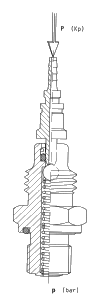
Connection of the specimen to the hydraulic system and determination of the coupling force required ( until the maximal flow is reached ) at gradually increased operating pressure.
The differences between test couplers and quick couplers result from the their different use. Whereas quick couplers are usually operated when the hydraulic system is at standstill, the test coupler’s main purpose is to aid in checking an maintaining the system while it is running.
For this reason the prerequisite is to have an acceptable ratio between the system operating pressure and the axial force needed to unseat the coupler’s valve.
The smaller the needed axial force, the easier it is to release the coupler’s valve whilst the system is under pressure. For standard test couplers the central bore diameter of 3,3 mm for the unlocking pin has become most common. The determination of the axial force, in dependence of varying operating pressures, therefor allows the valuation of different designs.
However, it also has to be considered that with an increase of the axial force there comes an increase of the reliability on the hermetic sealing of the coupler’s valve. It is therefor not possible to have an optimal design, but only an optimal compromise can be reached.

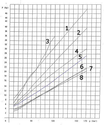
The obtained measurements were plotted to show the following reference line:

specimen:
1) PV 060
with conical coupler valve, sealed by O-ring
2) PV 031
axial sealing with flat valve seat, face side sealing by O-ring
3) PV 110
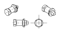
miniature Quick Coupler, as shown on the drawing
4) PV 040
design similar to speciment 1)
5) PV 010
design with metallic sealing
6) PV 070
design with ball-sealing dia. 4 mm
7) PV 050
design with ball-sealing dia. 4 mm
8) PV 020
design with ball-sealing dia. 4.75 mm (3/16'')
For comparison, the same test was performed on a typical quick coupler, as used on some construction machinery, in place of test couplers -(see type 3).
(The lack of a linear relation between the opening force and the operating pressure, is presumably due to the soft seal which at times finds different seating points on the conical contour of the valve seat. The recorded values are however decisively higher then those acceptable for TEST COUPLERS. Machines equipped with this type of accessories have to be stopped when the test hose is to be connected).
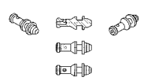
The negative effect of a soft seal of the type 4) and 8) is quite obvious in the illustration. The design is in both cases identical, the difference lays exclusively in the type of poppet used. The test sample corrisponding to the type 4) is equipped with a conical poppet with O-Ring, whereas the one corresponding to the type 8) is provided with a metallically sealing ball.

FLAT SEAT POPPET, SEALING ON ITS FACE THROUGH AN O-RING SEAL

CONICAL POPPET, EQUIPPED WITH AN O-RING, FOR SEALING IN A CONICAL SEAT (FLOW THROUGH A SMALL HOLE)

CONICAL POPPET, EQUIPPED WITH AN O-RING, FOR SEALING IN A CONICAL SEAT (FLOW EXCLUSIVELY THROUGH THE CLAERANCE BETWWEEN POPPET AND THE GUIDANCE BORE)

Independent of the recorded opening force, the metallic sealing will anyhow warrant a higher functional safety, as this sealing is not subject to ageing and wear.
