design characteristics: housing and valve sealing
Design options for the coupler body:
The design of the body determines the attributes of the test coupler, its strengths as well as its weaknesses!
In the following observations the denominations “ PV-…”refer to the design options for which closer examinations took place.
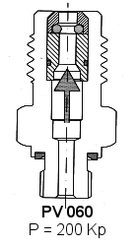
The various designs cause different axial forces that directly stress the body and the valve insert. The shown values occur at an operating pressure of 400 bar.
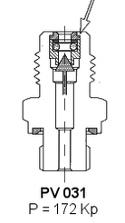
Designs with a flared-in valve insert
Here the axial force acts directly on the inverted flare. The fracturing of the flared shoulder can cause serious consequences, operating disturbances or accidents.
flaring process
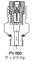
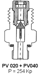
Designs with threaded valve inserts. The axial force must be born by the connecting thread. The size of the force is naturally determined by the diameters chosen. On some of the designs the axial forces can be considerable.
The sealing of the parts is obtained by O-Rings installed between the connection threads. These seals can extrude into the clearance of the thread but even more dangerous is the possibility that the threads become loose due to the effect of the pressure pulses of the system.
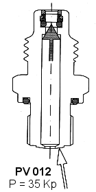
RAICO - design
This body design consists of a single piece and the axial force of P = 35Kp acts directly on the body (not on the flared or screw in inserts ).
There are no screwed together parts. There are no forces that act on the flared shoulder of the back end as it serves simply to retain the valve spring. This force does not exceed 1Kp and can therefor be neglected.
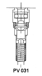
model with elastic axial sealing:
The flat shutoff poppet is sealed at its face on an O-Ring. Such an arrangement results in a relatively large sealing area with negative consequences on the on the coupling force ( see chapter “ Coupling Forces “ -->Reference Line 2 ).
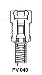
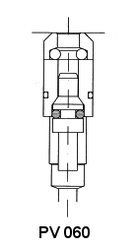
Elastic Radial Sealing With Tapered Valve
The sealing is achieved by an O-Ring which is mounted on the valve stem. As the valve stem needs to be guided there arise problems of flow restriction:
Whereas the model PV 040 has therefor a hole in the valve cone ( with cross hole ) with the dia. of only 1 mm, the model PV 060 provides a flow path for the full flow ( in the open state ) exclusively through the clearance between guiding stem and guiding bore.
On the models with elastic sealing there appear to occur no leakage problems at least until the seals are undamaged. But their integrity is threatened by machining burrs on the stems by ageing or by aggressive fluid media. The manufacturers of these designs trust that after assembly the products are leak proof, avoiding leakage test and rework. Ultimately the life of these designs is determined by the wear of the seals.
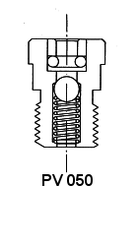
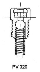
Models With Metallic Sealing, Mostly With Ball Valve.
Herewith very good solutions can be achieved, where no wear and ageing problems will appear. A ball can be a very reliable, cost effective construction element, provided the right quality for the application is selected.
However, to obtain a durable and trouble free sealing, the valve seat must be manufactured with great care
Rather doubtful are solutions wherein the sealing is attempted to be achieved by simply beating the ball down on its seat through an extension. Although the seat is thereby coined, the ball will also be deformed. When the ball is somewhat turned during successive actuation of the valve, leak problems are unavoidable.
Ball valves can also be advantageous in respect to the opening forces. This is evidenced in the chapter “Opening Forces” by comparing the reference lines 4) and 8) with each other. The two lines refer to identical body styles incorporating differing coupling valves. In the case of reference line 4) the test coupler is fitted with an elastically sealed valve ( Valve cone with O-Ring ) whereas reference line 8) is related to a coupler with a ball valve.
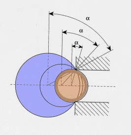
For a durable and trouble free ball sealing it is also important to have a suitable relation between the ball diameter and the seat diameter.
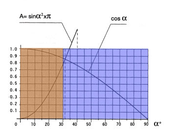
A relatively small ball will seal more easily as it will be wedged into the valve bore. Such a solution though is not recommendable for high pressure systems subject to pressure peaks. A reliable sealing with a relatively large ball requires a rather high manufacturing effort but offers optimal results when the valve seat is worked with the necessary care.
To assure inter change ability the valve seat diameter is to be considered unchangeable, the ball diameter can though be chosen at will. Based on empirical experiences it appears that an optimal ratio of diameters is given when the angle reaches the value of 32°.
