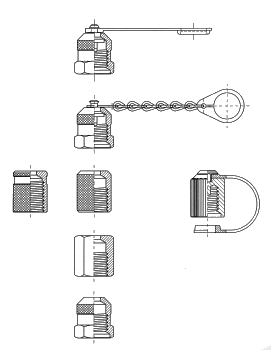
protection cap-design
These parts have the following functions:
* protect the coupling thread from dirt deposition
* prevent the external leak of any fluid that might have occurred due to a defective coupling valve.
To prevent the possible loss of the protection cap these are tied to the coupler housing by:
* metal chain
* or with the aid of a Nylon string or steel cable
* or with a pressure moulded tongue of thermoplastic material.
The protective caps are used for the said purpose as well as for swivel nuts on the miniature fittings
of measuring hoses.
Both these uses present similar technical requirements to the parts:
The protective caps have to be such that these can be screwed on by hand, using to fingers, ( therefor without the use of a wrench ) even while the hydraulic system is running. For this reason the cap’s cylindrical surface with the dia. of 19 mm is knurled

On a good contact surface each finger can apply a tangential force of 5 kp. This results in a torque of approximately M = 0,1 Kpm. Such a torque is usually sufficient to manually connect the test coupler up to an operating pressure of p = 210 bar.

To allow the coupling of the test coupler also at higher operating pressures it might be helpful to provide the protection cap in addition with a hexagon. Raico, as the first manufacturer, has therefor made the protection cap envelope partially knurled and partially hexagonal, with 19 mm hex flats.
This design, which allows the use of a wrench, may also be useful in emergency situations ( for instance if, for any reason, the coupler’s valve would be leaking ).

The different use of the protection cap is shown on the nearby drawings. In the picture A the part is used as the swivel nut on the miniature fitting of a test –hose. In the example B the part serves as the protective cap of a test coupler. During the insertion of the unlocking pin of the test hose fitting into the coupler, as shown in A , the pin seals off the test coupler by means of the O-Ring before it unseats the coupler’s valve ball.
When used as the protection cap, example B, the central pin is made shorter than an unlocking pin . Its length is just assuring the sealing by the O-ring but it does not unseat the coupler’s valve. This sealing function is an additional safety feature
The here shown picture illustrates the
many design variations of protection caps:

To tie the protection cap to the housing of the test coupler Raico provides two design options:

The first option offers considerable advantages. It does not restrict the turning of the cap, does not rattle and can not get twisted.
The version with the little steel chain is mostly reserved for special applications and can be found particularly in the shipbuilding industry where it satisfies specific design specifications. (Some safety specifications forbid the use of any kind of thermoplastic materials even for insulation of electric cables. In the general machine building industry there are no such restrictions)
The tear resistance and the observed deformation of the different designs are shown on the following diagrams. For the pressure moulded tongues the resistance can, in principle, be changed at will, by changing the cross section of the parts. When using PA-NYLON 11 in place of some less costly granulate the advantage is that the tongue, after some time, returns to its original length even following sever deformation.
The importance of the choice of the granulate can be seen by comparing the diagrams I) and II).


When using a little chain there is negligible deformation. As soon as the load limit is reached, the single chain links yield


To conclude the protection caps in thermoplastic material (not of steel ), frequently suggested for use, shall be tested. Thereof many different designs are offered. When one of the more robust looking designs is subjected to the burst pressure it is noticed that it bursts already at 160 bar even at the room temperature of 20° C.
At the normal operating temperature of a hydraulic system the resistance would be further reduced. This implies that if a safety factor of 3 is desired, the operating pressure of the system, on which test couplers with thermoplastic protection cups are used, should not exceed 50 bar.
