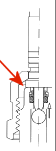
retainer- bushing assembly
The retainer bushings serve to hold in place the radial seals of the test couplers. At normal operating conditions this construction element is not subject to any load.:
-
With uncoupled test-hose the internal pressure acts on the shut off valve and can not affect the retainer bushing.
-
With the test-hose coupled and the coupler valve unlocked the shoulder of the unlocking pin rests on the retainer bushing holding it in its seat.
Loading of the anchoring of the retainer bushing occurs only during the activation of the couplers’ valve. The unlocking pin already seals off at the O-Ring ,the locking valve is partially open but the shoulder of the pin is not yet in contact with the retainer bushing. Now the bushing is subjected to a considerable load ( at the pressure of 400 bar it may reach 75 kp ) which can move the retainer bushing off its seat.
It is therefor very important that the retainer bushing is firmly anchored.

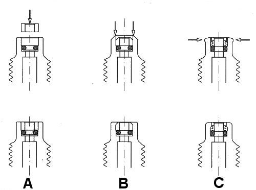
The various mounting solutions are shown on the drawings here below:

A) shows a mounting possibility based simply on friction force. It requires very close machining tolerances on all components, not an easy task at mass production on automatic lathes.
B) illustrates the assembly by of flaring the face of the body which, compared to the solution A), already improves the safety remarkably. Though it must be remembered that under high load conditions, face side flares are easily ruptured.
C) In the RAICO design solution the retainer bushing is held in place by a radial deformation of the body. to this purpose the retainer bushing is provided with a step and the coupler body is machined a rim of excess material. The deformation is achieved by pushing a ring shaped form tool over the coupler body. Thereby the excess material of the rim flows plastically towards the inside blocking the retainer bushing firmly and securely in place.
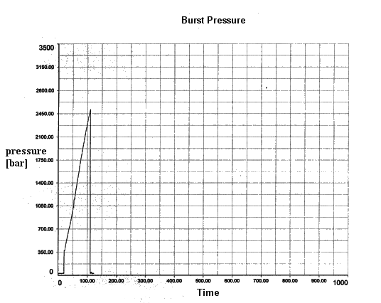
To provide the relevant evidence the burst test was performed as blow described:

Recorded maximum pressure p = 2.514 bar
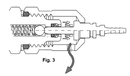
To simulate the loading conditions that prevail in practise the test was performed as shown in illustration 3) : The use of a prolonged unlocking pin, allows to open the test-couplers’ valve while the O-Ring seal is already engaged and the shoulder of the pin has not yet reached its stop. In stead, there remains enough space between the pin shoulder and the stop to allow the retainer bushing to extrude as soon as the gradually increasing operating pressure pushes it out of place. Thereby the appearing failure is made visible right away, by a substantial leakage flow.

